Fencing:Testing Methods For Penetration Resistant Armor
Appendix - Testing Methods for Penetration Resistant Armor
A drop tester is used to ascertain that materials meet the penetration resistance standard of the Society, and is required every two years for penetration resistant armor, with the exceptions noted above in Appendix 1 under the definition of Penetration Resistant Armor.
The only acceptable alternate to the use of the test described here is a commercial 550N garment punch test devices, manufactured by sources acceptable to the Society Fencing Marshal, Deputy to the Society Marshal. Such a device shall be used in accordance with its instructions.
Procedures for creating a drop tester
It is important not to deviate from the construction specifications given below without approval, as seemingly minor changes can affect the test results.
There are three major parts to the tester, the drop probe (the weighted piece), the guide tube, and the round frame (3-inch flange, below) over which the fabric to be tested is clamped. The actual test method is detailed below but here is a brief overview:
Clamp the fabric over the 3-inch flange, balance the guide tube over the center of the fabric, and drop the weighted drop probe down the middle of the guide tube, as shown in Figure A3.1, below. If the rod on the end of the falling drop probe punches through, the fabric fails, if it doesn't punch through the fabric passes.

These instructions describe how to build a drop tester for carrying out these tests. It won't take very long to build, and will not be very expensive, but does need one special part.
Parts list
- 1-inch nominal diameter 18 inches long Black Pipe stub from any do-it-yourself/hardware store, plumbing supply house, etc, this is heavy, iron pipe used for natural gas.
- 1 inch nominal plastic cap for pipe above (screws onto end of pipe)
- 0.156-inch (5/32-inch) "plus tolerance" diameter gage pin, 2-inch length, Class Z or ZZ.
- Footnote: A gage pin was found to have a more consistent edge, or shoulder, than other types of bar stock. If the edge is too sharp or too rounded, the results of the drop test will be affected.
- drill bit stop or collar (piece that goes on to a drill bit to set the depth of a hole)
- epoxy (the solid grey type such as JB Weld works well, clear epoxies do not hold up as well)
- 2-inch nominal diameter PVC or equivalent (material doesn't matter for this), at least 30 inches
- 3-inch PVC 3-inch Male Adp. DWV (short section of PVC, has *external* threads on one end)
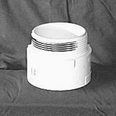
Figure A3.2a. 3-inch PVC 3-inch Male Adp. DWV - 2 hose clamps, 2.5-inch to 4-inch range (large enough to fit over 3-inch adapter above)
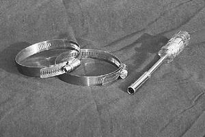
Figure A3.2b. Hose clamps. - screwdriver or nut driver (to operate test)


Construction Tools
- Power drill with 5/32-inch drill bit
- scale capable of measuring to about 1/2 oz or 10 g (can go to post office and use theirs)
- (optional) saw (some way to cut the PVC pipe above, or can have it done at hardware store)
- (optional) file, sandpaper, to smooth PVC
Construction
Step 1: Make the guide tube
- Cut the 2-inch nominal diameter PVC tube to 23.6 inches (60 cm) in length. Try to make the ends square (so when it is placed on a flat surface on either end, it stands up straight). A wood saw is fastest for this, a hack saw will work as well, or get it cut at the store you buy it at.
- Drill three holes with the 5/32-inch drill bit near the bottom end of it for air release when the probe drops, the location doesn't matter as long as they are within a couple of inches of the bottom.
Step 2: Make the drop probe
- First get a gage pin, at the supplier above. Do not modify the end, these pins are used because they are consistently manufactured. Make sure that the pin is clean of any oil or other chemicals that would keep the glue from sticking properly.
- Drill a hole in the center of the 1-inch plastic cap with the 5/32-inch drill bit.
- Now put the drill collar on the gage pin with about half of the gage pin sticking out of one side, and apply epoxy. Before it dries, put more epoxy on the gage pin, and shove it into the hole in the cap, with the drill collar on the outside, curved side of the cap. The exact type of drill collar isn't important, it is just to provide some extra grip to keep the gage pin from breaking loose and sliding up into the drop probe with repeated impacts, since the PVC hole alone isn't a great glue surface.
- When you have it put together and the epoxy is still wet, put it on a flat surface and slide the gage pin down until it bottoms out where the plastic cap sits on the flat surface. It will look something like Figure A3.3 (below), when done. Make sure the gage pin doesn't dry at an angle (it should be parallel to the iron pipe, keep checking visually as it dries). If the pin isn't sticking straight out of the cap, your drop tester will not work properly.
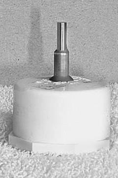
Figure A3.3a. Plastic cap with gage pin and drill collar sticking out, all epoxied together (gray) 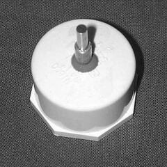
Figure A3.3b. Plastic cap with gage pin and drill collar sticking out, all epoxied together (gray)
- After the epoxy dries, screw the cap on to one end of the pipe (make sure not to get epoxy on the threads, you may want to remove it later!).
- Weigh the drop probe assembly, using a good scale. It should be able to measure to half an ounce or 10 grams, a postal scale at the post office could work for example. If possible, try to use metric units - it will make calculations easier later on.
- The height from which the probe will be dropped is directly dependent on the weight of the probe. Since not all cast iron pipe will weight the exact same amount, and the length of the pipe may be off by a small portion, calculate the exact drop height for the probe being constructed. Use the formula below for a 1.5 Joule drop energy to calculate the drop height for your tester.
- In Metric units: 15306 / (the probe weight in grams) = drop distance (in cm)
- or, in American units: 212.6 / (the probe weight in ounces) = drop distance (in inches)


- Plug the measured drop probe weight into one of the formulas and calculate the drop distance. It should be between 10 and 20 cm (4 and 8 inches), if not, you found a really unusual pipe stub and should not proceed further.
- Lay the probe next to the PVC tube from the first step, slide it "up" next to the PVC guide tube until you have that calculated drop distance from the bottom of the PVC tube to the gage pin sticking out of the drop probe, and mark the top end of the drop probe where it lies next to the top of the PVC guide tube (tape, etc.), as shown in Figure A3.4 (below). That is the mark you will want to line up with the top of the PVC tube when you drop the probe. Some of the probe will stick out of the top end of the tube when you have it all together vertically and give you a place to grab it. (The reason metric units are easier is that it's easier to measure fractions of a centimeter than it is fractions of an inch.)

Step 3: The Clamps and Frame
No modifications needed here, you just need the two hose clamps and the threaded flange, along with a screwdriver or nut driver to tighten the hose clamps. Do not substitute other parts for the flange with outside threads, as the grip on this surface has a big impact on fabric slippage, which has a big impact on whether the test passes or fails armor.
It is suggested that you get a nut driver (like a screw driver, but with a socket head) for tightening and loosening these hose clamps, it is much easier to use than a screw driver as well as being safer.
Procedures for Use of a Drop Tester
The basic idea behind this test is to drop a known weight a known distance to give a known impact, giving a pass/fail verdict to "unknown" fencing armor. This document will tell you how to use the tester to test armor. See above for how to choose and build these items. You should have all six pieces shown in Figure A3.5, below, including a guide tube, drop probe (unique to your tester), 3-inch threaded PVC flange, two hose clamps and a screw driver or nut clamp to tighten the hose clamps.
You should only use your probe with the guide tube it was designed for. Interchanging these items between testers may produce inaccurate results.

- You need a hard surface to work on. Surfaces such as pavement, an extremely sturdy table, concrete, etc are good choices. Carpet or grass are bad choices; they absorb impact and make the test too easy for armor to pass.
- Start by setting the threaded PVC flange thread side up and laying the test fabric over it, and loosen the first hose clamp so that it will fit easily over the fabric and flange but pull the fabric somewhat taut as it is pushed down. Tighten that hose clamp, put a second one on and slide it down to touch the first then tighten the second one. It should look something like Figure A3.6. You may want to invest in a 5/16-inch nut driver (like a screwdriver with a socket head). It will prevent gashes on your hand from slipped screwdrivers. Note that if you didn't push the first hose clamp far enough down (you may want to lean on it a bit with the screwdriver or nut driver), the second hose clamp won't stay on when you tighten it; it will just barely fit if you do everything right.
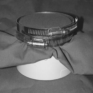
Figure A3.6 - Fabric clamped onto flange with two hose clamps. Notice that the second one will protrude a bit above the level of the fabric with thicker fabrics, but it should still be tight if you push everything down enough.
- Then, place the guide tube on the center of the clamped fabric. Steady it with one hand, trying not to push downward on the fabric.
- Put the drop probe into the guide tube, lowering it to roughly the mark that shows where to drop it from, and slowly tilt the guide tube back and forth until the drop probe seems to hang freely, not lying against a side. (You are using the drop probe like a plumb bob to get everything vertical.) Line up the mark exactly with the top of the guide tube, and drop the probe. It should look like Figure 7 below just before you drop it.
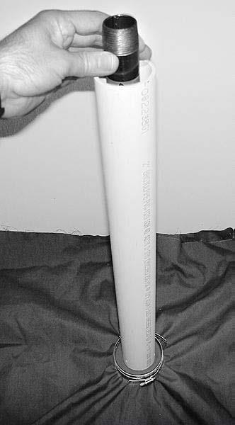
Figure A3.7 - Drop Tester just before making a test drop. Note that the guide tube is centered on the clamped fabric, and the drop probe is being used as a plumb bob to make the guide tube vertical.
- Let go of the probe.

Now examine the fabric. If the pin punched through anything beyond the top layer of fabric, the material fails. If the pin did not punch through, recheck the top hose clamp with a gentle tug to be sure it is still tight. If there was slippage it will often get loose, so this is a good check to be sure the fabric didn't slip. If it's loose, you need to redo the test. If it's not loose, the fabric passes. Always be sure to check the tightness of the fabric after the drop.